A number of different models have been developed to model batteries within the past decade[i]. Most of these models fail short of predicting the total behavior of the battery due to the complex nature of the interfaces between the electrodes, electrolytes and the separator.
Most information about the complex behaviors of batteries are obtained using Impedance Spectroscopy studies. The impedance spectrum is then fit to a complex equivalent circuit model that explains the frequency dependence of the spectrum. The standard practice in the literature is to attempt to convert these models to time domain in order to model the battery behavior accurately. Due to complexity of the impedance behavior, this conversion is done numerically and thus it suffers from computational complexities and inaccuracies.
We are proposing a change in paradigm where the impedance model doesn’t need to be transformed at all. Instead, the applied waveform can be transformed into the frequency domain (via well-established algorithms like Fast Fourier Transform). Once this transformation is done, the battery response can be calculated in the frequency domain by a multiplication at every frequency of interest. This gives a AC voltage response of the battery. Then, a simple inverse transfer into time domain will yield the required response. Finally, DC response of the battery that is obtained experimentally is added to its AC voltage response.

Measured and calculated voltage responses when Highway-FET Driving Schedule[ii] applied to NiMH battery
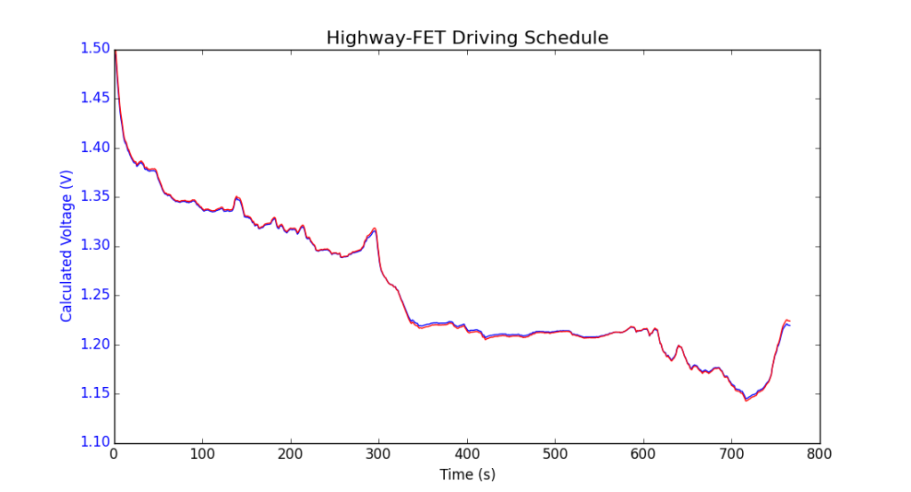
Measured (in red) and calculated (in blue) voltage responses when Highway-FET Driving Schedule applied to 350F supercapacitor
[i] Castano S et.al. Ener. Conv. And Man. 2015(92) 296-405 or Santhanagopalan S et. al. J. Power Sources 2006(156)620-628
[ii]United States Environmental Protection Agency, Dynamometer Drive Schedules.
https://www.epa.gov/vehicle-and-fuel-emissions-testing/dynamometer-drive-schedules/, 2017 (accessed 5.10.15)